What's new
  • Please do not post any links until you have 3 posts as they will automatically be rejected to prevent SPAM. Many words are also blocked due to being used in SPAM Messages. Thanks!

Completed Fixed angle 32" monitor stand (Pinball) & Front full width controller box

sswilson

Moderator
Staff member
Joined
Dec 9, 2006
Messages
24,716
Location
Moncton NB
Tying up loose ends while I'm watching the paint dry, and the shims print..... :)

filed divit.jpg

I may need to take a bit more off of this to clear the protruding electronics casing, but it's curved down to the next lowest part and I don't think it's going to need much removed for clearance.

sawed rear feet.jpg

Made the command decision to remove the excess from the back "feet". My original plan was to have one board width out the back (like I have in front) for extra stability, but having the extra 90 deg extended out almost as far as an extra board width would have so I figured that was good enough.
 

sswilson

Moderator
Staff member
Joined
Dec 9, 2006
Messages
24,716
Location
Moncton NB
Coming into the home stretch (for the main monitor part of the project at least).

side shims installed.jpg

3 side shims printed and installed.

Shim Fit Overall.jpg

Seems to be reasonably level between the two sides now....

Shim Fit front measurement.jpg

Last shimming job is the front. I've got the height for the left side dialed in, and this measurement on the right is what I need to model my front shims on.

print job start.jpg

Last pair of shims (hopefully they won't need to be adjusted) queued up and printing.
 
Last edited:

Sagath

Moderator
Staff member
Folding Team
Joined
Feb 7, 2009
Messages
6,641
Location
Edmonton, AB
How did you decide on the playing angle for the screen? I'm no pinball guru, but I believe that different boards can have different angles. Also, I know for a fact stores could adjust the angle to increase/decrease difficulty as I remember a tech doing it when I was a teenager.

Might be an interesting mod, obviously it wouldnt affect the true gameplay, but might give you a bit more 'simulation' feel perhaps.
 

sswilson

Moderator
Staff member
Joined
Dec 9, 2006
Messages
24,716
Location
Moncton NB
How did you decide on the playing angle for the screen? I'm no pinball guru, but I believe that different boards can have different angles. Also, I know for a fact stores could adjust the angle to increase/decrease difficulty as I remember a tech doing it when I was a teenager.

Might be an interesting mod, obviously it wouldnt affect the true gameplay, but might give you a bit more 'simulation' feel perhaps.

Driven primarily by physical desk space. The monitor itself is 27" high in portrait mode which would take up the whole desk/table if laid flat. A 50 deg angle leaves enough desk/table space for me to have the controller in front of it.

I had the ability to adjust beyond 50 deg with my previous setup (gas shock mount) but 50 seemed like it was the sweet spot.

edit: Strangely enough (I didn't plan it this way) the footprint of the stand is almost exactly 27" deep as currently built.

edit 2: Viewing angle is also a consideration.... an IPS screen has relatively decent viewing angles, but even the best screens still have some form of drop-off as the angle increases. The higher the angle, the less consistent the colour/details between the bottom and top of the playing field.
 
Last edited:

sswilson

Moderator
Staff member
Joined
Dec 9, 2006
Messages
24,716
Location
Moncton NB
BTW.... I'm an idiot..... :(

Been out of basic geometry for too long.... no wonder I had to shim up the joints when I did 2 50 deg ones instead of one 50 and one 40... :(

I've shimmed up and filed down well enough that I've got solid joints at those points, and attempting to fix that issue at this point would muck up my level, but damn... what a rookie mistake. As it stands, I threw my square onto the joints and they're both awfully close to 45 deg so it's a bit steeper than I had initially intended but not by so much that it's going to make a huge difference to footprint.

With that in mind.... if I were doing this again I'd just do 45 deg angles on both for a simpler build.
 

clshades

Well-known member
Joined
May 18, 2011
Messages
6,263
Location
Big White Ski Resort
H
BTW.... I'm an idiot..... :(

Been out of basic geometry for too long.... no wonder I had to shim up the joints when I did 2 50 deg ones instead of one 50 and one 40... :(

I've shimmed up and filed down well enough that I've got solid joints at those points, and attempting to fix that issue at this point would muck up my level, but damn... what a rookie mistake. As it stands, I threw my square onto the joints and they're both awfully close to 45 deg so it's a bit steeper than I had initially intended but not by so much that it's going to make a huge difference to footprint.

With that in mind.... if I were doing this again I'd just do 45 deg angles on both for a simpler build.
haha yes. Always has to equal 90 degrees at some point. So if one is 35 the other is 55. :cool:

On a side note my work safe claim (WCB) has been approved, so the updates better be daily man! LOL.
 

sswilson

Moderator
Staff member
Joined
Dec 9, 2006
Messages
24,716
Location
Moncton NB
H

haha yes. Always has to equal 90 degrees at some point. So if one is 35 the other is 55. :cool:

On a side note my work safe claim (WCB) has been approved, so the updates better be daily man! LOL.

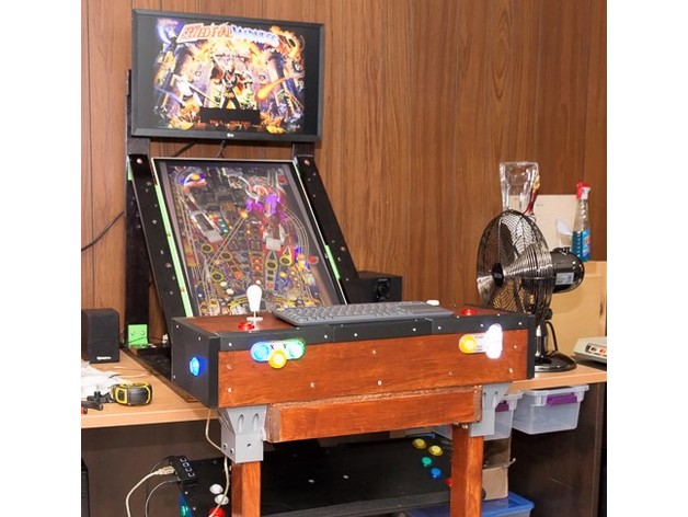
Heh... well the build's pretty much done so I can give you the parts list for the stand as it sits....

Wood is all 1X3" (my salvaged stock was somewhere around 2 3/4" so adjust accordingly, but the inside frame measurements need to be based on the monitor/tv's width)

6 X 30" (main frame)

3 (or 4) X 22.5" (crossbeams)

2 X 17" (inside crossbeam, between main frame 1 flush with rear crossbeam, 1 Protruding 1 1/2" facing aft that the front of the monitor will rest on)

2 X 23" (inner frame monitor support, one full length, one cut 3 pieces for access to ports)

Hardware (Not listing nuts / washers, but assume 1 nut + 2 washers for each fastener)

30 M4 X 35mm (main countersunk construction)

15 8-32 2" (Inner frame support, but you can easily get away with 12, 1 3/4" would work better, and I've ordered 45mm M4 that I intend to replace these with when they come in)

4 8-32 X 1 1/2" (90 deg angle braces)

8 8-32 X 1 1/4" (2 per 50/40/45 deg angle bracket)

16 #10 X 3/4" Wood screws (2 per angle bracket)

4 #10 X 1" Wood screws (1 per 50/40/45 angle joining the two pieces of wood)

Assorted Hardware

you'd also need various shims depending on the specific monitor/tv as well as attaching hardware for it.


That's what went into this particular build. Dowels at the joining points would negate the need for so many machine screws, and barring that a person could probably get away with wood screws, but the mechanic in me likes the strength you get from 4 machine screws / joining surface as well as the option that offers of loosening everything up in order to square the frame if the need arises.

Aside from my messed up angles, this thing is built like a tank. :)

3D printed parts I've used that could be replicated either with wood or metal are the angle brackets (I'm wondering if a 2" hinge would work well for the non-90 deg support) and the shims (inner support and front).

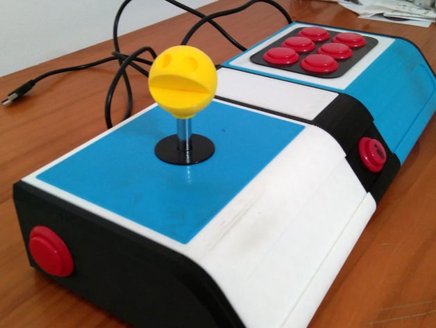
This is the arcade joystick/button kit I ordered that seems to have worked well..... It's currently OOS, but there are similar kits from the same manufacturer with different coloured buttons than the kit I ordered...


Lastly... here's the 3D printed controller I put those switches into.... you could conceivably make a wooden box, or (like the video I posted in another thread...) use an amazon shipping box... :) .


additions

16/07: Added the top monitor mount so 2 X Vesa plates (I 3D printed them), an extra 4 X 35mm M4s for mounting the monitor, 4 X 1 1/2" 8-32 , and a scrap piece of wood wider than the vesa plates.

17/07: For what it's worth... here's the shims I used for this particular monitor


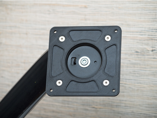
18/07: These are the 90° brackets and vesa plates I used (not my designs)


It's included in the thingiverse shim link, but here's the direct tinkercad link for the flipper mount if anybody is interested...


https://www.tinkercad.com/things/eU3NdGGAZMs

Flush mount 2X3" brace print for front cabinet legs...


20/07: Added a front keyboard ledge so 1" plywood cut to 17" wide (X2) and whatever length required for the keyboard.

3/08: Working on converting the keyboard tray into the controller "body" thus added a "flipper mount" model to the thingiverse files and included tinkercad link here.

15/08: Added the flush mount 2X3" leg mount print I used on the front cabinet


22/08 Added link for controller cabinet trim
 
Last edited:

sswilson

Moderator
Staff member
Joined
Dec 9, 2006
Messages
24,716
Location
Moncton NB
Pretty much done, no running pinball pics yet as I have to straighten out where it's going before I get it completely set up.

First Front Shims.jpg

Tape for shim.jpg

Yesterday was spent playing with these front shims... the uncomplicated one was good on the first print... the larger one took 5 prints to get right and even then still required some manual shimming to get square and level. (I used layers of UHMW tape).

Front Vesa.jpg

Rear Vesa.jpg

While I was waiting for the various front shim prints to finish I rigged up the top monitor mount. It needed to be wider than a single 3" crossbeam and I wanted it slightly higher than the current top of the stand so I used a couple of 75 / 100 Vesa mount adapters to "join" an extra 3" piece of wood on top. In my case, the monitor I'm using is a 75mm mount so I secured to the two pieces of wood in the 100mm holes, if it had been a 100mm monitor mount I would have secured between the 75mm holes. I didn't bother trying to figure out a way to secure the two pieces of wood to each other as they're sandwiched between two strong printed mounts.
 
Last edited:

sswilson

Moderator
Staff member
Joined
Dec 9, 2006
Messages
24,716
Location
Moncton NB
And now... the completed build.... :)

Overall Front no monitors.jpg

There's the full frontal. The monitor rests on the LH shims to account for the thinner "top", the two shims on the bottom are holding the monitor in place and is also where most of the monitor's weight is distributed. The smaller shim on the RH side is for centering the monitor in the frame.

Getting the right distance for the RH front shim was easy enough, but shimming the LH one so that the monitor was square between the two sides was a major pain in the arse and took damn near the whole day.

Overall Front main monitor.jpg

The star of the show!!! Fits great now that it's shimmed up, and is heavy enough that I don't feel I need to worry about securing it on the back. I've got a couple of ideas for securing the top that I can work on at my leisure, but as it sits, there's no way that monitor is coming out of that position unless somebody tips the stand completely forward.

Overall Front both monitors.jpg

And here's the Co-Star!!!! I think I actually get a bigger kick out of the upper monitor mount than I do out of the main one. The monitor sits well forward of the rear "foot" so it's not inclined to tip backwards even without the larger monitor in place, and once the larger monitor is in place there's absolutely no concerns about the stand being tipped backwards without some kind of drastic force being applied to it.

Rear Vesa monitor installed.jpg

both monitors rear.jpg

The top monitor is secured to the stand with 4 M4 machine screws through both pieces of wood and both vesa adapters so it's not going anywhere, and here's a rear view of the whole build with the monitors installed. The small square in the upper LH corner of the white LG monitor is the menu access button, and is why the monitor is oriented in this particular direction in spite of that having the ports on the far side, and requiring "portrait mode flipped" in windows settings.

I'll post up an after-action report on the whole build sometime over the next few days, but aside from a few hiccups I'm ecstatic over how it turned out! It's a little rough around the edges (the salvaged wood already had random mounting holes in it, and I added a few extras of my own... :) ) but the darker coloured wood and SS screws framing the monitor at first glance almost makes it look like it's a bare screen that's been stripped from the frame.
 
Last edited:

Latest posts

Top