- Location
- Moncton NB
No guarantees but this is the link I came up with through google.....
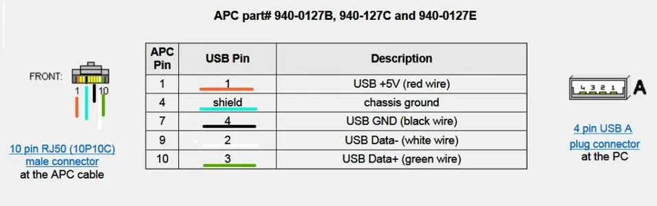
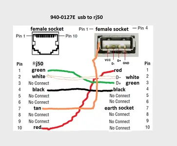
APC USB cable schematic pinout and wiring @ pinoutsguide.com
Does anybody who made these back in the day have the pinouts saved?
Edit: if you read through the comments for that link the critical (and apparently not obvious) key is to use RJ50 not RJ45
APC USB cable schematic pinout and wiring @ pinoutsguide.com
Does anybody who made these back in the day have the pinouts saved?
Edit: if you read through the comments for that link the critical (and apparently not obvious) key is to use RJ50 not RJ45
Last edited: